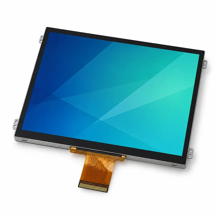
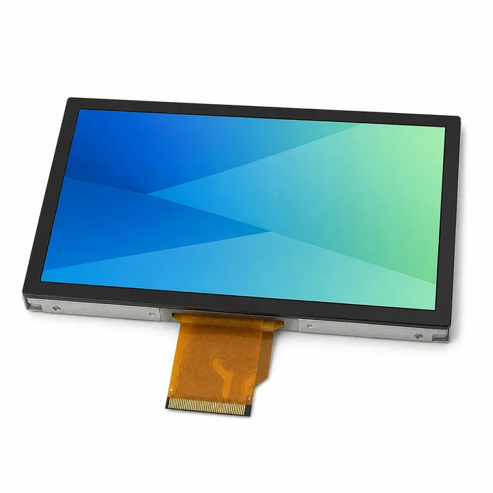
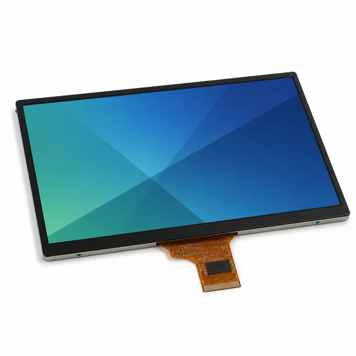
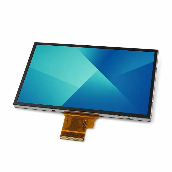
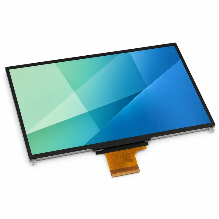
How to select a standard TFT-LCD display module
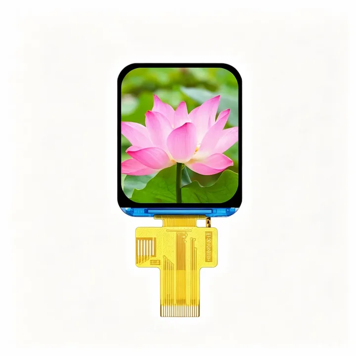
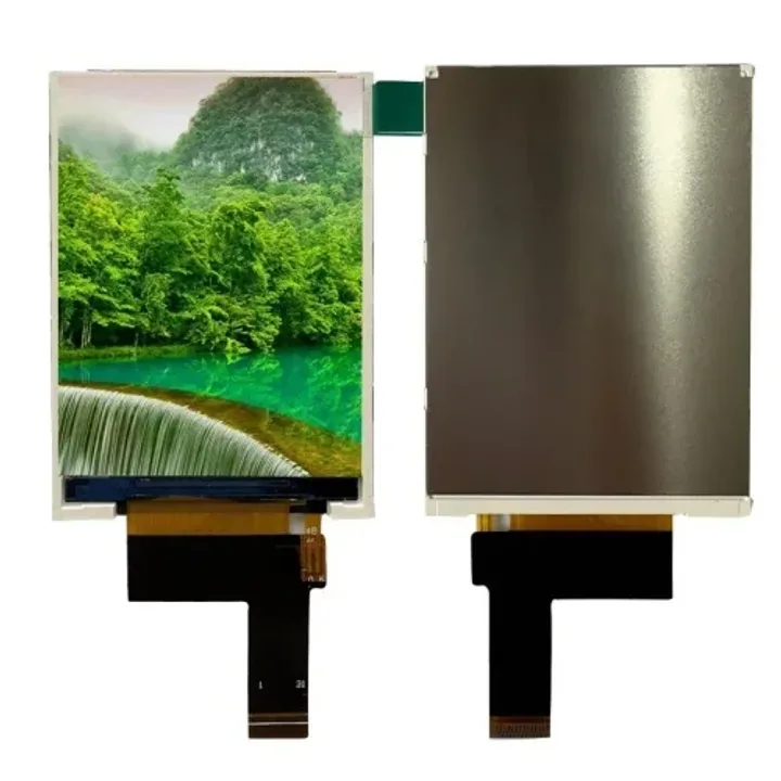
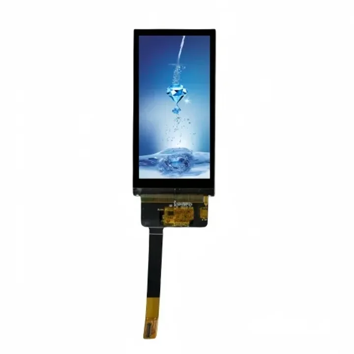
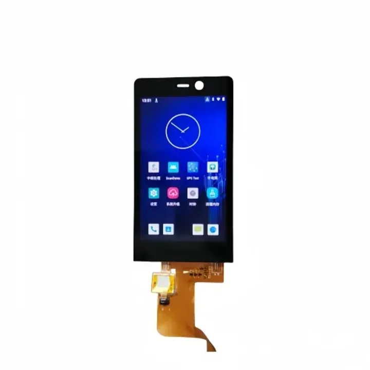
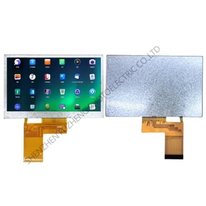
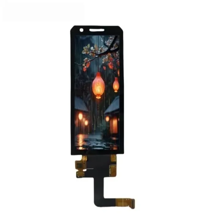
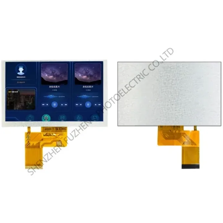
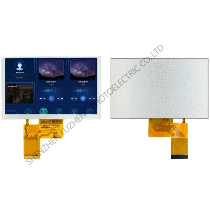
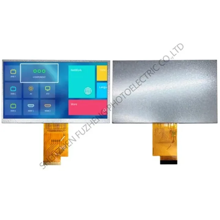
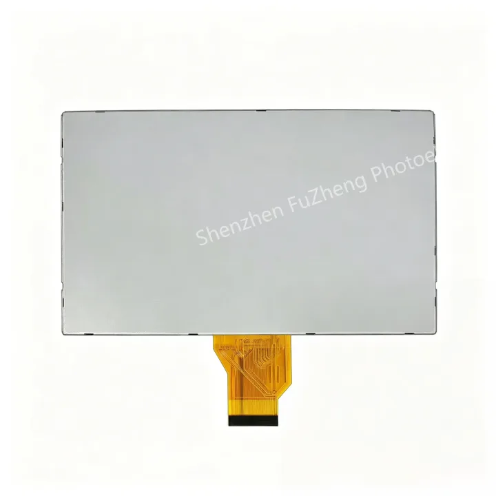
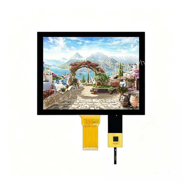
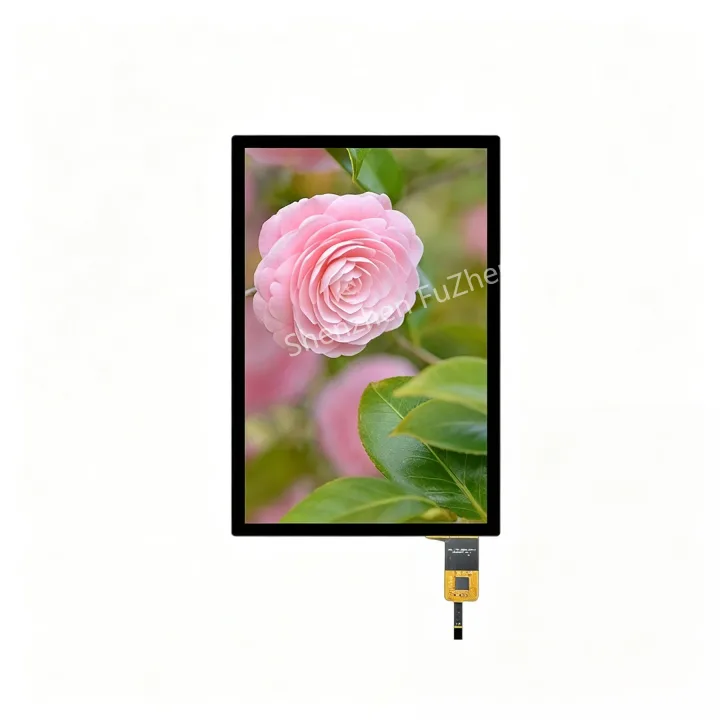
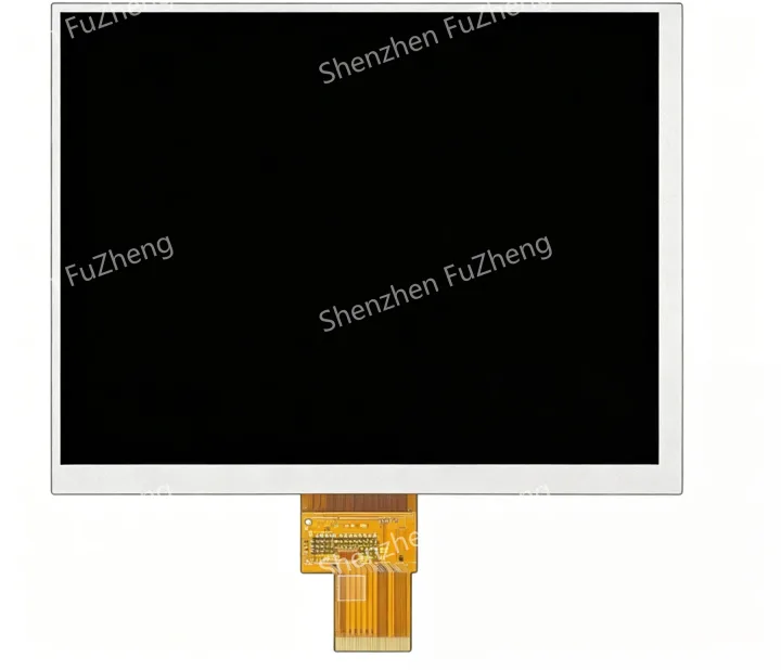
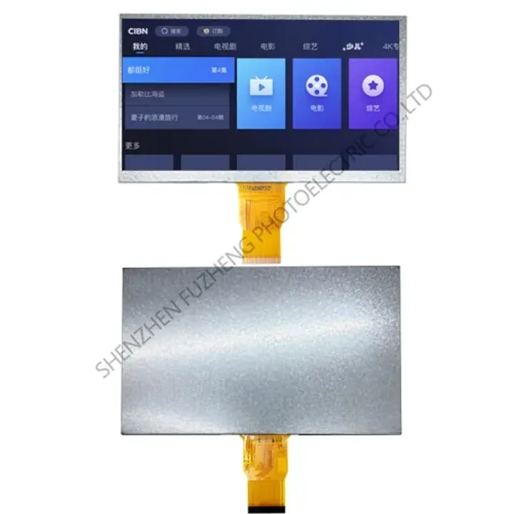
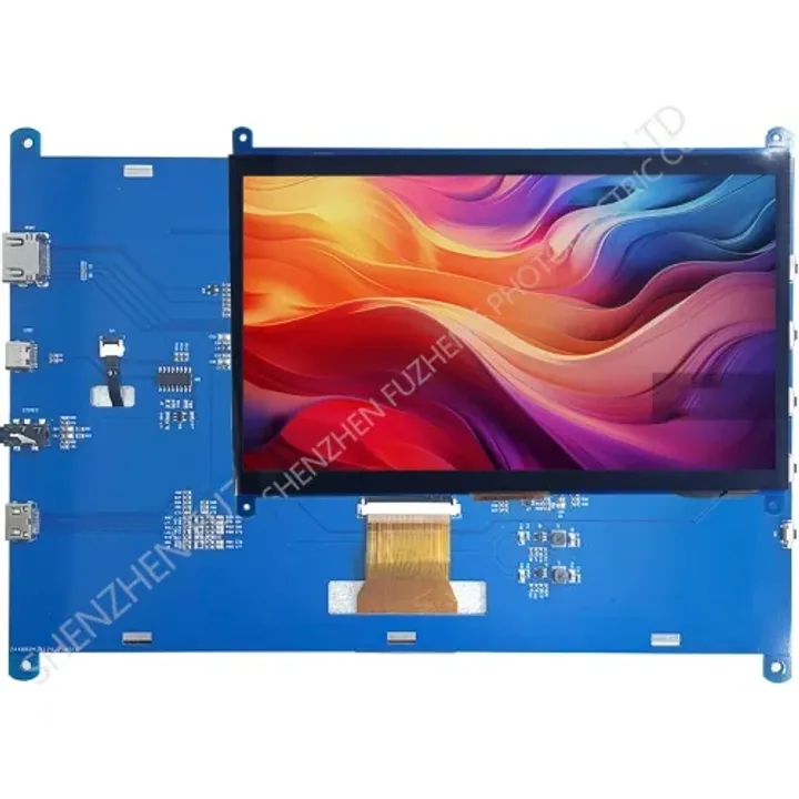
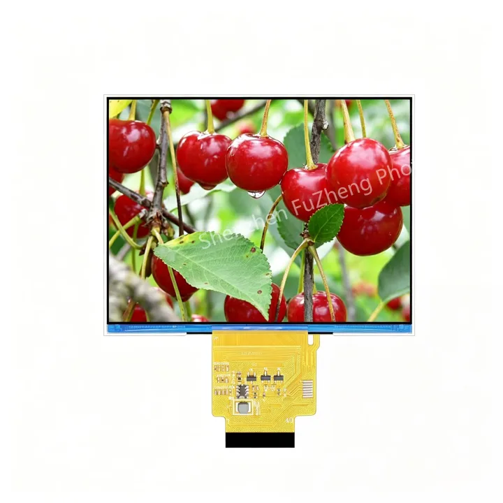
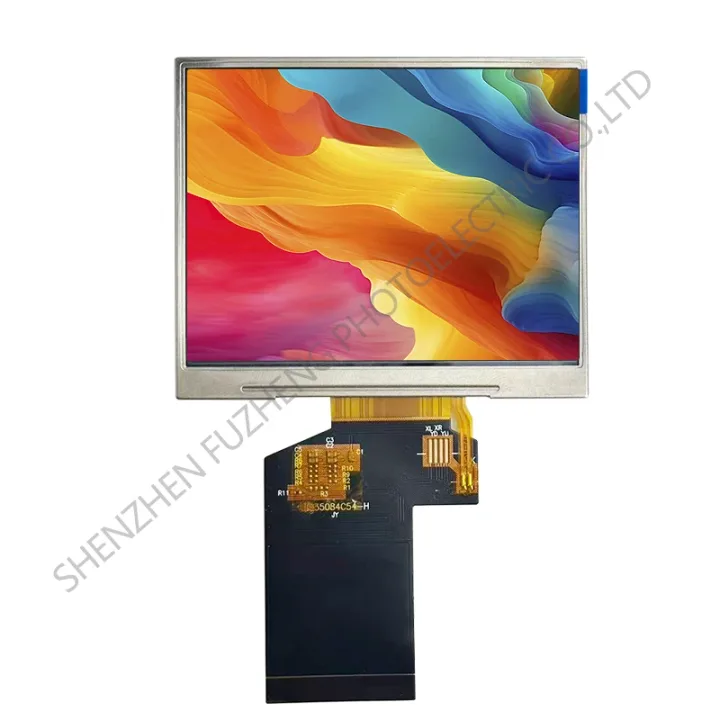
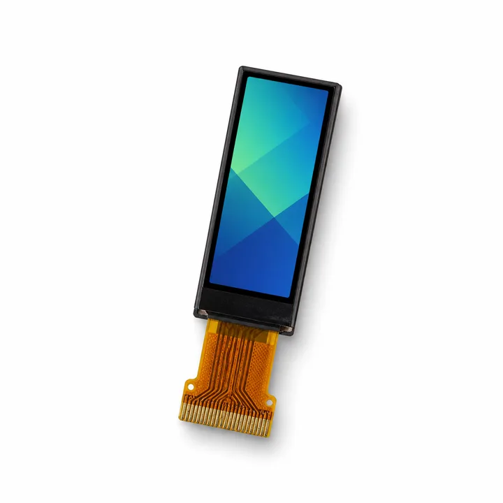
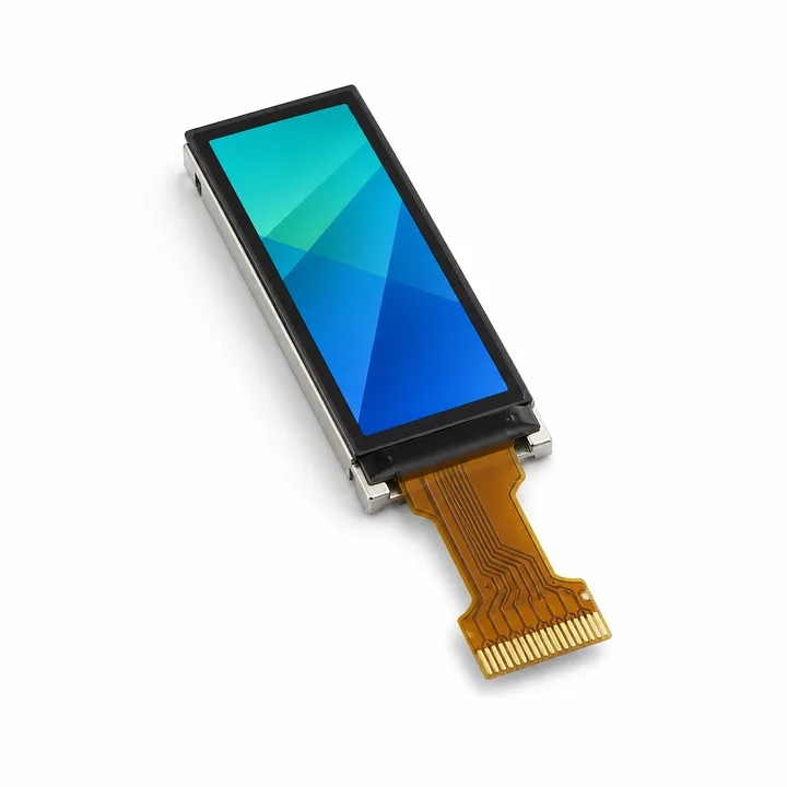
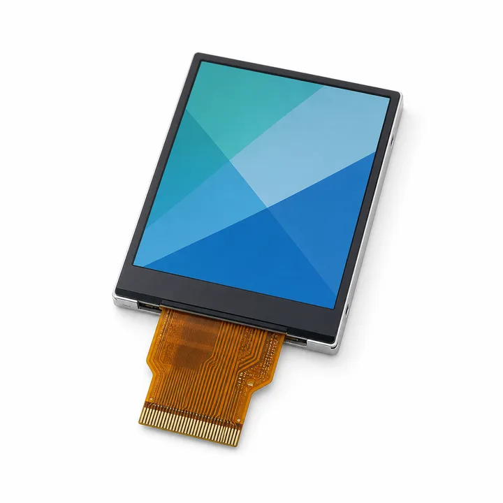
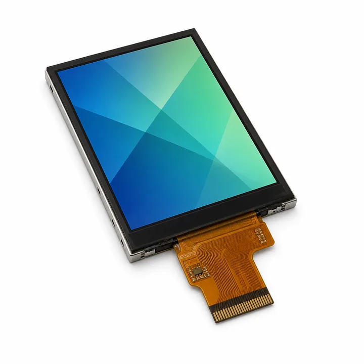
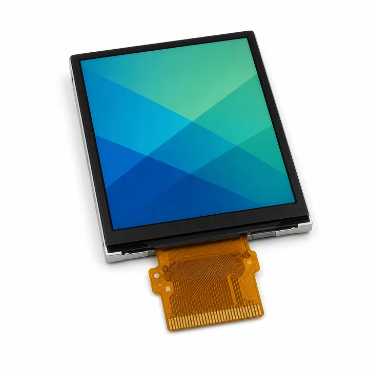
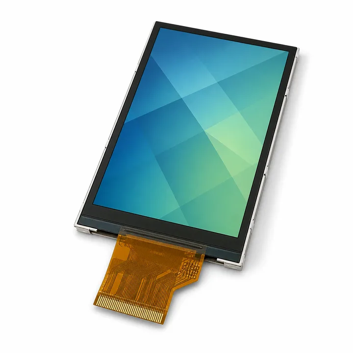
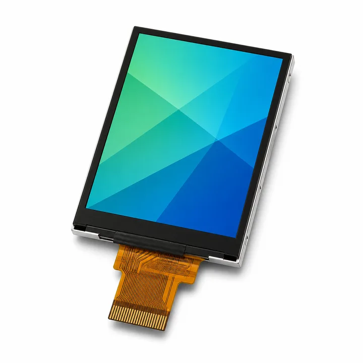
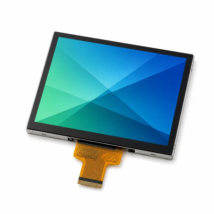
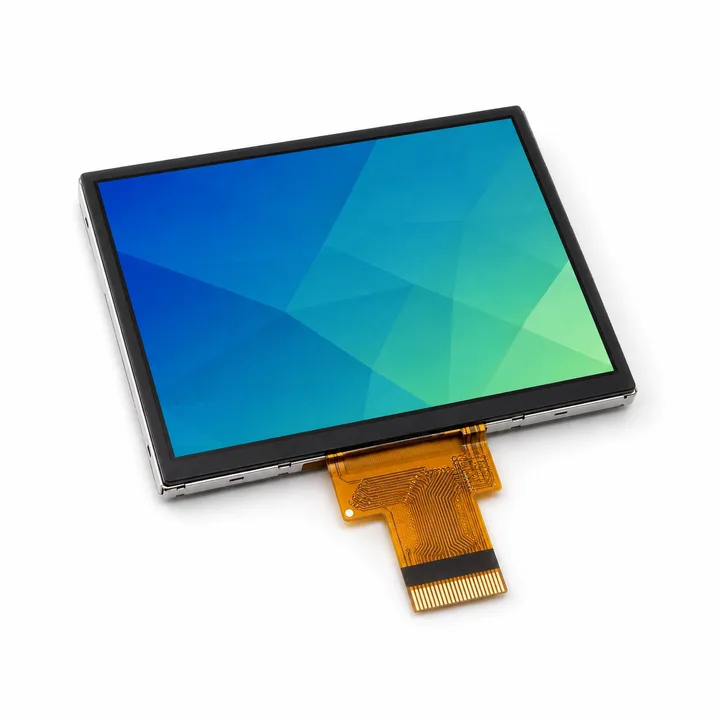
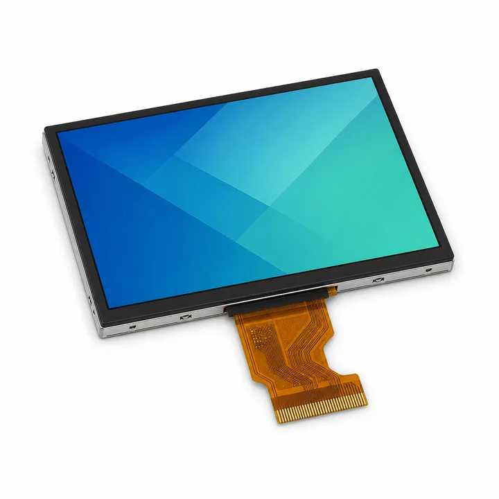
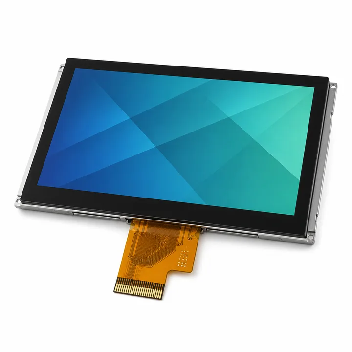
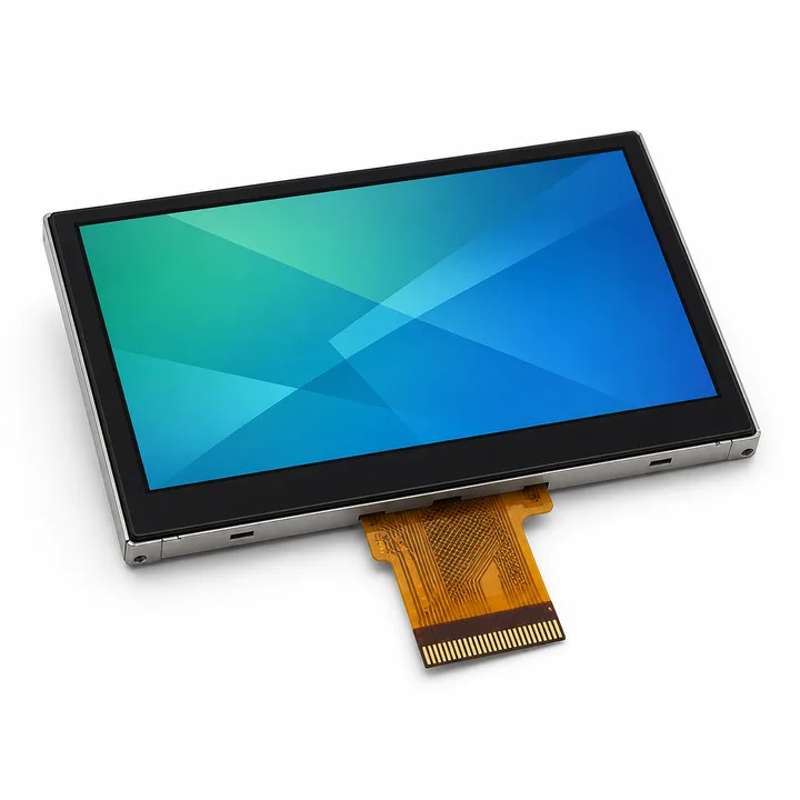
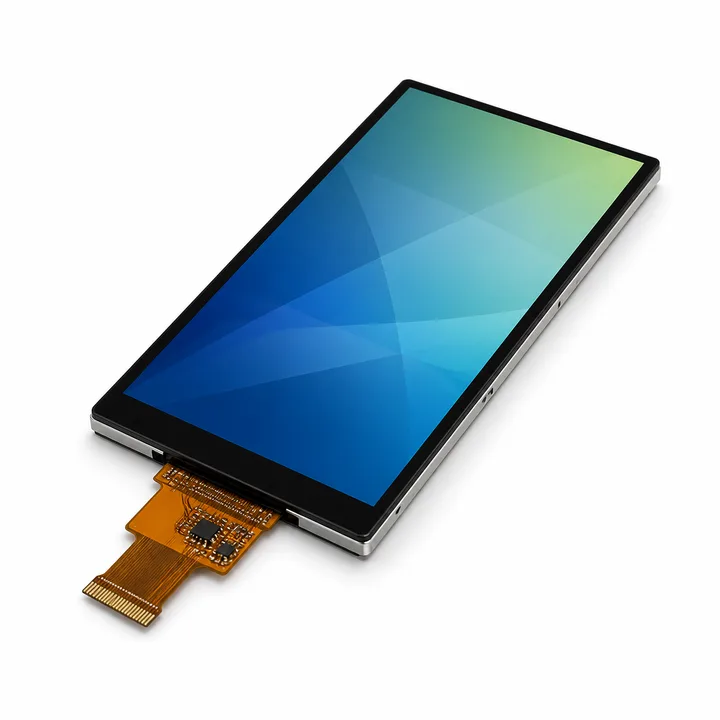
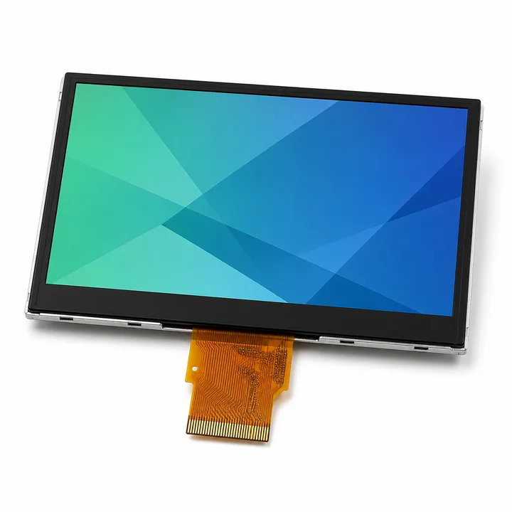
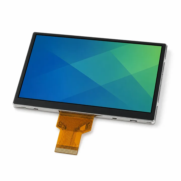
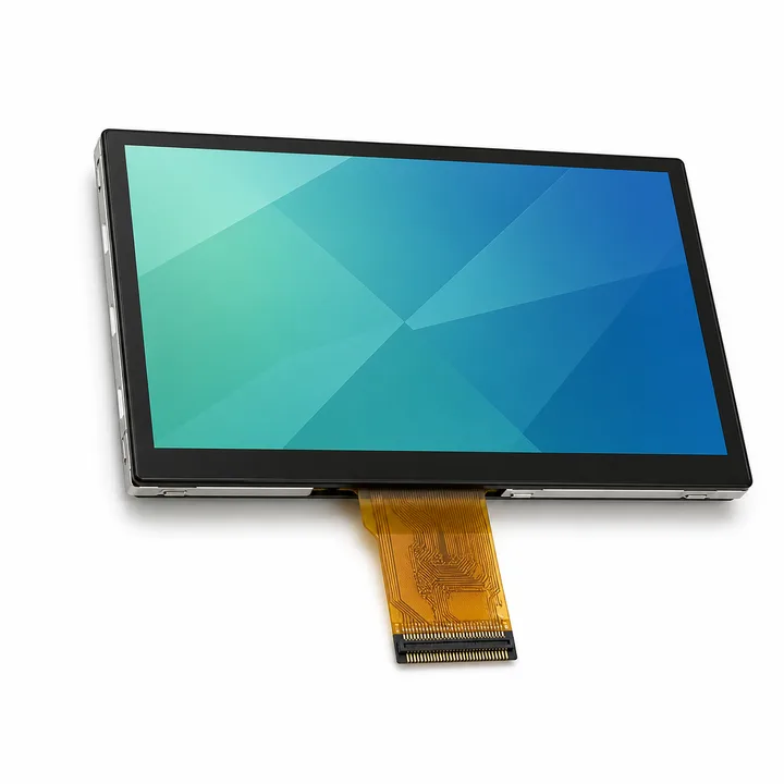
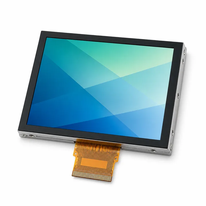
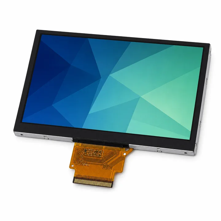
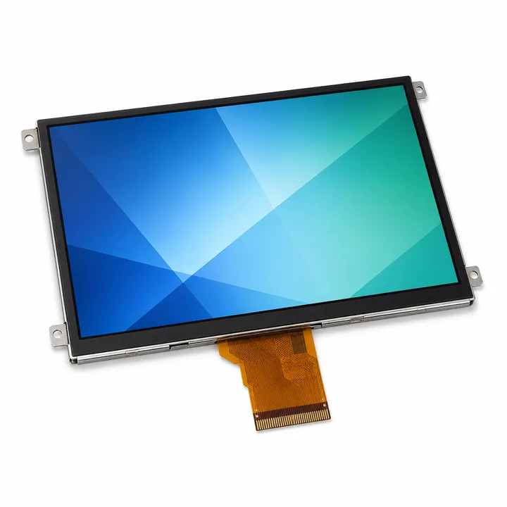
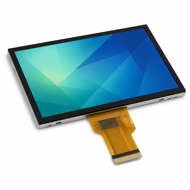
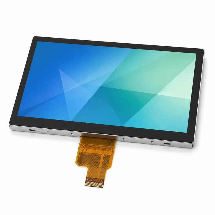
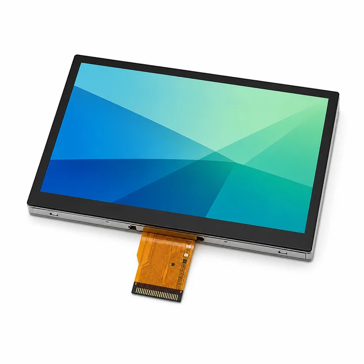
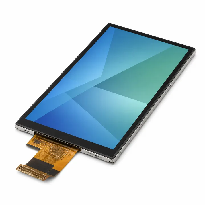
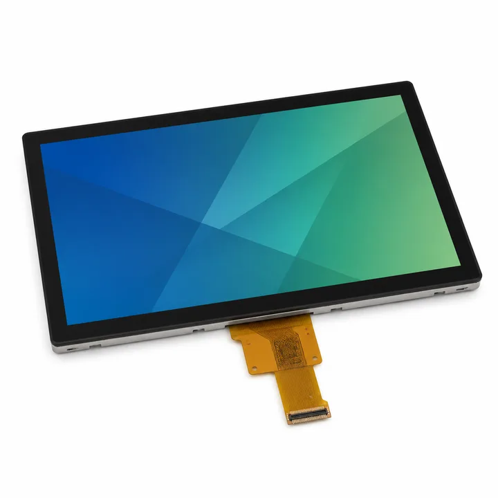
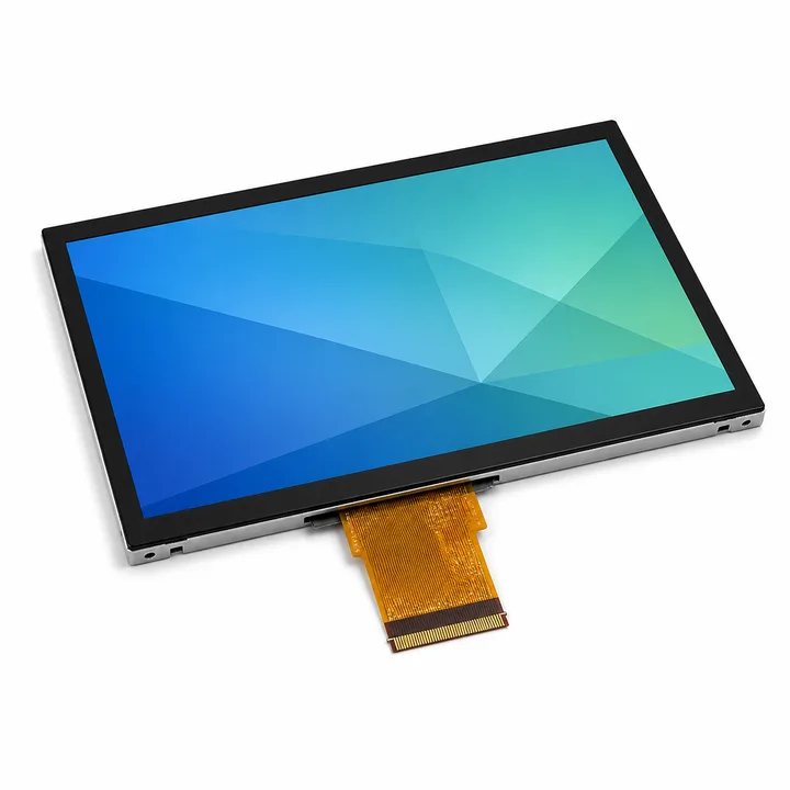
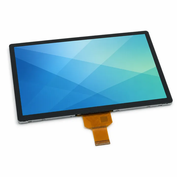
A standard TFT-LCD module is not selected by diagonal size alone. The module outline, active area, pixel resolution, interface, viewing direction, brightness, touch stack and connector position all affect whether it can be integrated into the final product. Begin with the product enclosure and host electronics, then narrow the catalog to modules that satisfy both.
Use the TFT-LCD display selection guide for a step-by-step engineering checklist. For operator panels and control equipment, continue with the industrial HMI display integration guide.
Compare the parameters that change the design
| Selection area | What to confirm | Why it matters |
|---|
| Mechanical format | Module outline, active area, thickness, mounting space and FPC exit | A matching diagonal size can still conflict with the bezel, enclosure or cable path. |
| Resolution | Pixel count, aspect ratio and UI content density | Resolution affects legibility, graphics workload and the interface bandwidth required from the host. |
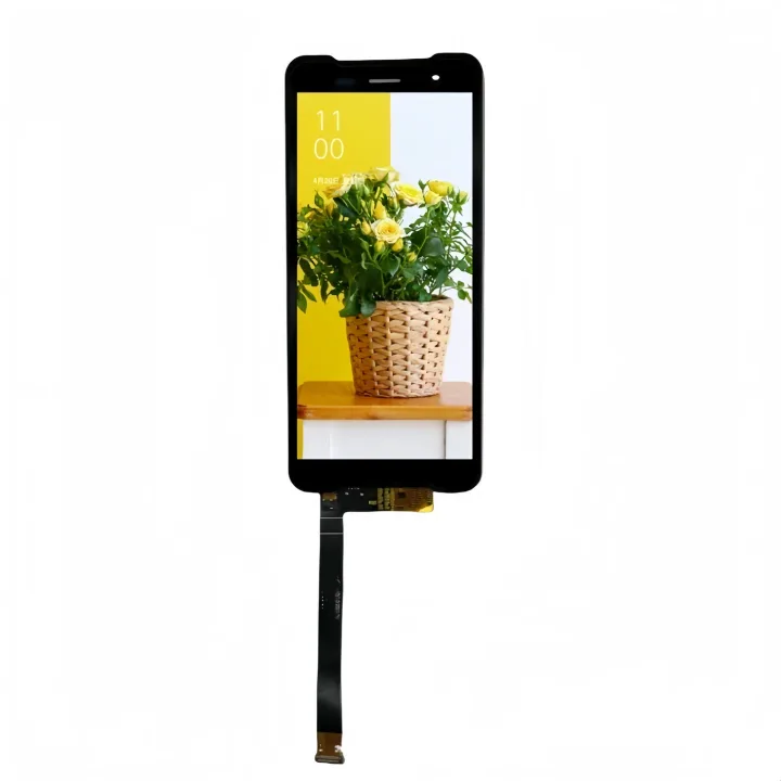
| Host interface | RGB, LVDS, MIPI or another published interface | The display timing, connector and electrical design must match the processor or controller board. |
| Viewing and optics | IPS or published viewing direction, brightness and surface treatment | The correct target depends on operator position, ambient light and the front assembly. |
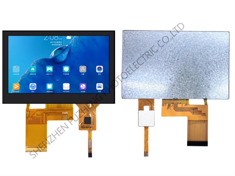
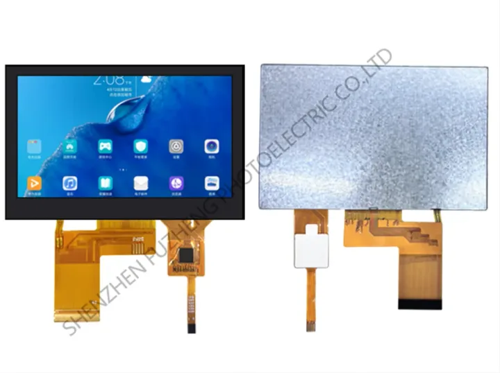
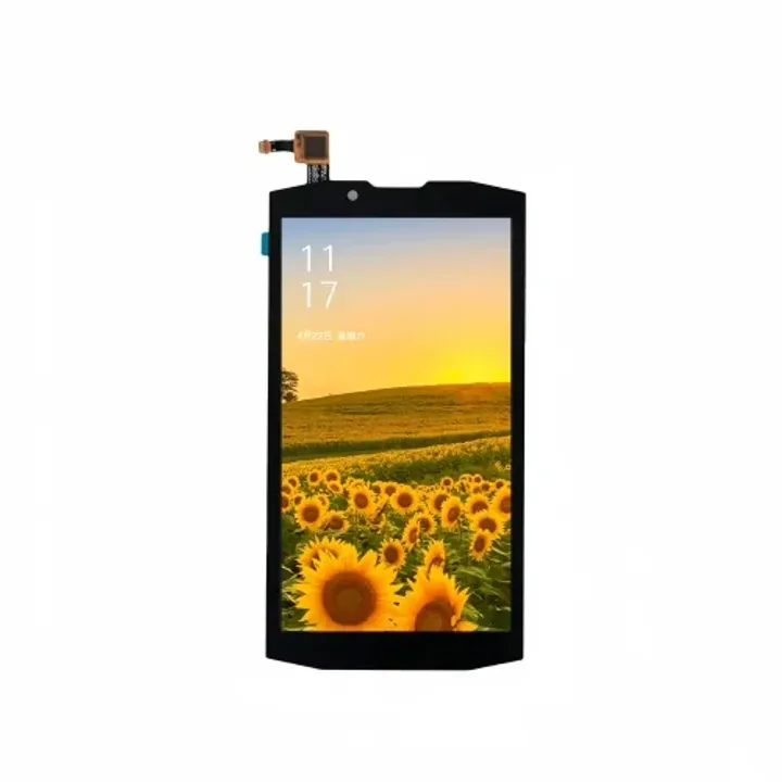
| Touch and cover lens | Touch technology, cover-lens dimensions, bonding and decorative treatment | The complete stack changes thickness, optical performance and mechanical tolerances. |
| Environment | Operating temperature, storage conditions, vibration and expected service use | Catalog values must be checked against the equipment environment before sample approval. |
RGB, LVDS and MIPI are not interchangeable labels
Interface choice should follow the host platform and the complete electrical design. RGB commonly carries parallel pixel data and timing signals. LVDS uses differential signalling and is frequently considered where the module and host architecture support it. MIPI DSI is a high-speed serial display interface used by compatible processors and modules. The published pin assignment, voltage, lane or bus configuration and timing must be reviewed for the exact module; the interface name alone is not enough to establish compatibility.
Plan the touch and front assembly together
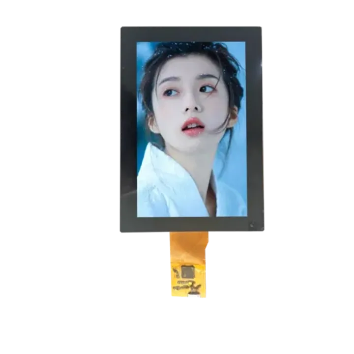
If the product needs capacitive touch, include the cover lens, touch sensor, bonding approach, controller, grounding and enclosure opening in the same review. A touch-enabled module may change the overall thickness, visible area and connector routing. For industrial controls, glove use, water on the surface, electromagnetic conditions and the required front-panel treatment should be defined before a sample is ordered.
Brightness should follow the actual viewing environment
Higher luminance is not automatically the best answer. Indoor operator panels, portable equipment and outdoor terminals have different ambient-light, power and thermal constraints. Confirm the published luminance, viewing angle, contrast behaviour, cover-lens transmission and any anti-glare or optical-bonding requirement as one optical system.
Move from catalog comparison to sample evaluation
Shortlist modules using published specifications, then request the latest drawing and confirm interface timing, connector or FPC, touch stack and environmental requirements. Evaluate the sample in the real enclosure with the intended host system and representative lighting. Send these constraints through the TFT-LCD engineering RFQ so the review begins with a controlled requirement set.