
TFT-LCD Quality Control & Manufacturing
Connect the exact display record, manufacturing sequence, sample checks and project-specific reliability requirements in one reviewable quality path.
Quality advantages
- Source-backed production scope
- The supplied archive includes a display-module line, process map and equipment overviews.
- Checks around the module
- Review optical, electrical, touch and mechanical questions against the exact product definition.
- Project-defined validation
- Confirm conditions, sample size and acceptance criteria before reliability work begins.
Quality starts with one controlled product definition.
A display can only be evaluated clearly when the model, drawing, interface, optical target, touch stack and application conditions refer to the same project record.
Fuzheng's quality path is presented around reviewable evidence: the source module record, the supplied manufacturing materials, an agreed sample plan and documented changes. This keeps the website useful without turning an unverified certificate or capacity claim into a sales promise.
- Module record
- Exact model, published specifications and source-matched media
- Engineering context
- Drawing, interface, FPC, touch, cover lens and enclosure
- Sample decision
- Questions the evaluation must answer before the next project stage
- Evidence status
- Archive-backed facts separated from items requiring current confirmation
-
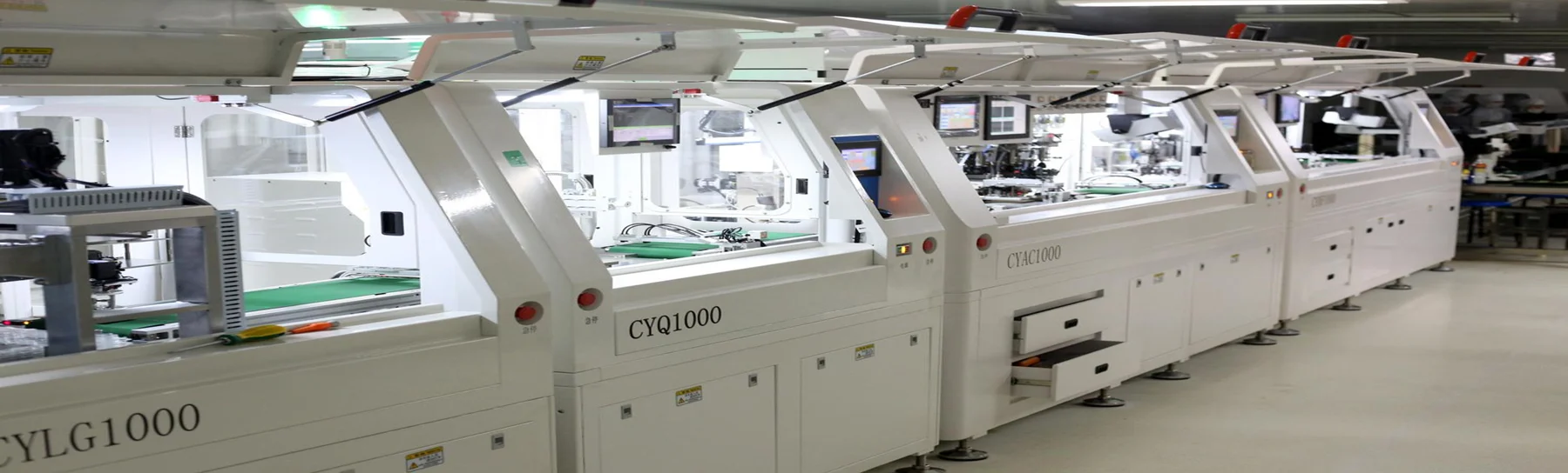
Fully Automatic Polarizer Attachment
LCD grinding and cleaning
-
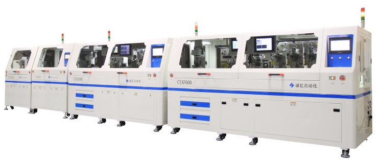
Fully Automatic COG & FOG Line
Chip and FPC bonding sequence
-
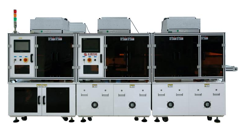
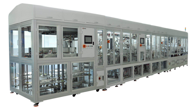
Fully Automatic Optical Bonding
Touch and display bonding
-
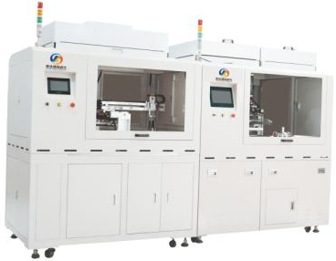
Fully Automatic Backlight Assembly
Backlight module assembly
From cleaning and bonding to OQC and packing.
The supplied company profile documents the main LCD module assembly sequence. The English process below keeps every archived checkpoint readable on desktop and mobile.
Archive-backed process-
Cutting & cleaning
Prepare the LCD surface for controlled assembly.
-
Polarizer attachment
Apply the polarizer to the cleaned LCD.
-
LCD cleaning
Remove particles before ACF work.
-
COG ACF attachment
Apply conductive film for chip bonding.
-
Chip pre-bonding
Position and tack the driver IC.
-
Chip main bonding
Complete controlled chip bonding.
-
FOG ACF attachment
Prepare the FPC bonding interface.
-
FPC alignment & bonding
Align and bond the flex connection.
-
Functional test
Check electrical and display operation.
-
Protective silicone coating
Protect the bonded connection area.
-
Protective paper attachment
Cover and protect the IC area.
-
Backlight assembly
Assemble the backlight to the LCD stack.
-
Alignment
Confirm layer and module alignment.
-
Backlight soldering
Complete the backlight electrical connection.
-
Functional retest
Recheck module operation after assembly.
-
Insulating tape attachment
Add electrical and mechanical insulation.
-
Appearance inspection
Review workmanship and surface condition.
-
OQC inspection
Perform outgoing quality-control checks.
-
Packing
Pack the approved module for handling.
-
Warehouse transfer
Move released goods into controlled storage.
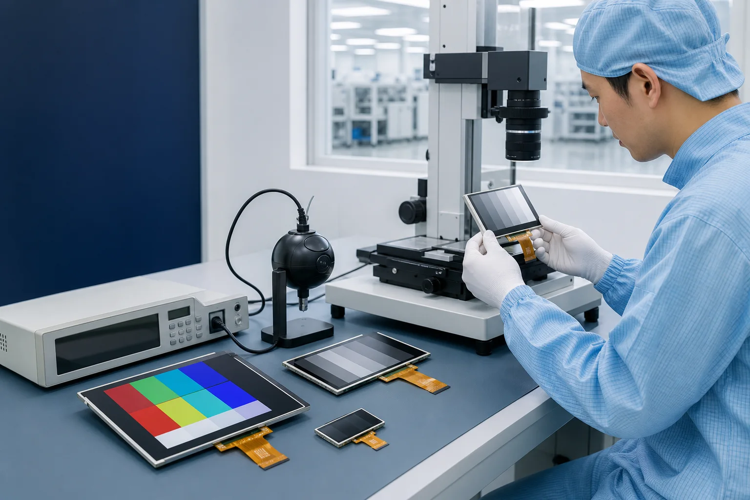
Four inspection questions around every sample.
The right acceptance plan follows the final product. These review areas help engineering and purchasing teams define what should be checked before a sample is ordered.
- 01Optical & appearance
- Agree how display state, visible defects, brightness, color and uniformity will be evaluated against the selected module record.
- 02Electrical & interface
- Check power, interface behavior, backlight drive, connector assignment and startup behavior in the intended host system.
- 03Touch & front assembly
- Review touch response, visible area, cover lens, bonding stack and alignment with the enclosure opening.
- 04Mechanical & handling
- Compare outline, thickness, FPC orientation, mounting, surface condition and packing needs with the approved drawing.
Test conditions belong to the application, not a generic promise.
A handheld terminal, industrial HMI and outdoor controller do not need the same evidence package. The test plan should follow the selected module specification and the operating risks of the final assembly.
The supplied equipment overview references temperature and humidity chambers, thermal shock, dimensional measurement, ESD, luminance and color analysis, salt spray, vibration and impact equipment. Before quotation, confirm which items apply, the sample quantity, conditions, duration and acceptance criteria.
- EnvironmentTemperature storage or operation, humidity and thermal cycling where required
- Electrical robustnessESD and operating behavior defined around the host product
- Mechanical stressVibration, impact or handling checks selected for the application
- Optical stabilityDisplay state, brightness, color or uniformity compared before and after testing
Confirmation boundary: the archive shows equipment categories and example conditions; current availability and the final test plan require project confirmation.
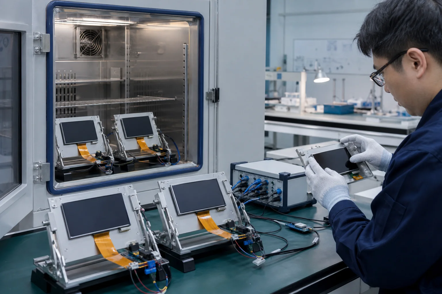
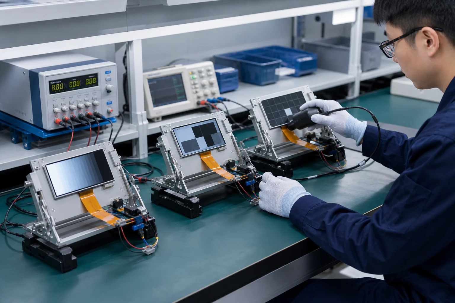
Published reliability reference.
These conditions are translated from the supplied company profile. Applicability, current availability, sample quantity and acceptance criteria must be confirmed for each project.
- Storage
- +70 °C high / -20 °C low; 96 hours
- Damp heat
- 60 °C, 95% RH; 96 hours
- Thermal shock
- 70 °C for 30 min / -20 °C for 30 min; 30 cycles
- ESD
- Contact discharge: +/-4 kV; air discharge: +/-8 kV; LCM nine-point check
- Salt spray
- 5% solution; pH 6.5-7.2; 24 hours; chamber at 35 +/-2 °C
- Vibration
- 5-20 Hz; 1-3 mm amplitude; 1 hour
- Aging
- 60 °C, 95% RH under operation; 30 days for new products / 24 hours for mass production
Keep the approved definition attached to the next decision.
Quality communication becomes more useful when every observation points back to the same model, revision, drawing and application requirement.
- 01
Identify
Use the exact model, revision, product record and available drawing.
- 02
Define
Set sample checks and application conditions before evaluation begins.
- 03
Evaluate
Record electrical, optical, touch and mechanical observations together.
- 04
Control change
Carry confirmed drawing, interface or requirement changes into the next discussion.
Send the constraints before the sample.
Attach the enclosure or window drawing, host interface information, existing display datasheet, target environment and the acceptance questions that matter to your product.
Send project requirementsDefine the evidence before the test.
Use these questions to separate available source material, project requirements and items that still need confirmation.
What quality evidence is available on this page?
The production-line image, LCD module process map and equipment overviews come from the supplied Fuzheng website archive. Quantitative capacity, certificate and universal test claims remain unpublished until current supporting files are approved.
Does every TFT-LCD or OLED module use the same reliability test plan?
No. Temperature, humidity, thermal cycling, ESD, vibration, impact or other validation should be selected around the module specification, application environment, sample stage and buyer requirements.
What should a buyer provide before sample evaluation?
Provide the target module or display requirements, host interface, enclosure or window drawing, touch and cover-lens needs, operating environment, expected quantity and the decisions the sample must answer.
How are generated images distinguished from factory evidence?
Generated quality-review scenes are captioned as illustrative visuals. Archive-sourced production and equipment images are separately captioned as supplied Fuzheng source materials.
Bring your display requirements to an engineer.
Share the target size, resolution, interface, touch, brightness, environment, quantity and project stage.