Application context
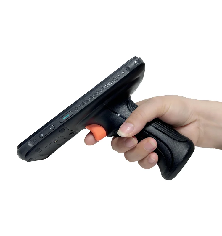
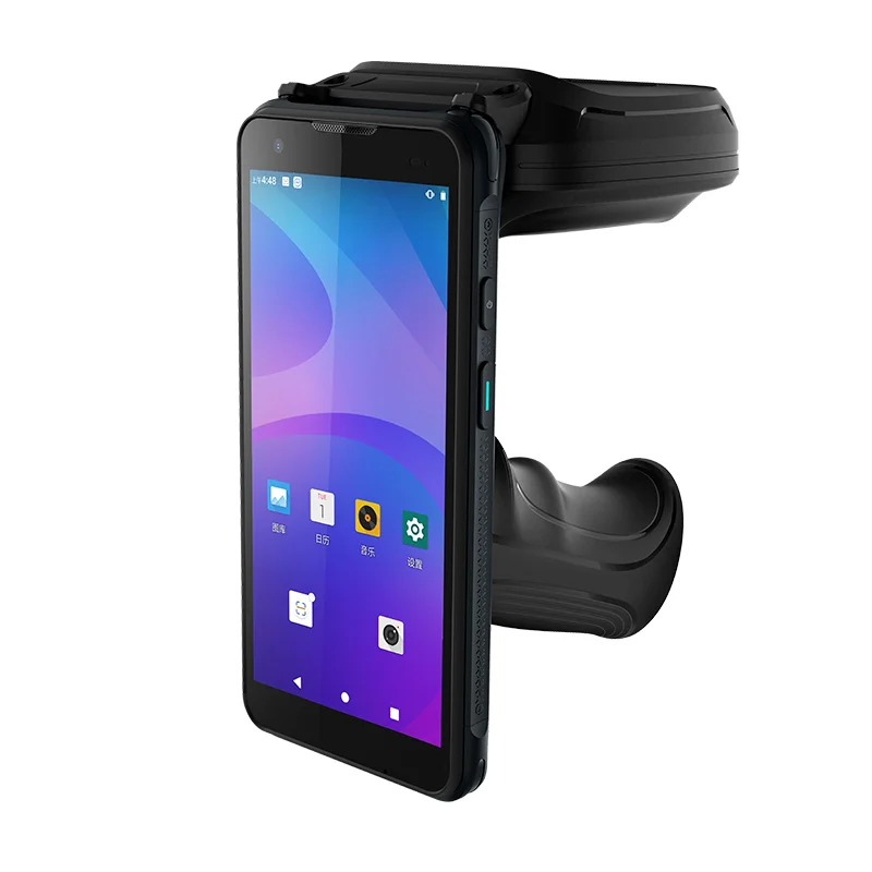
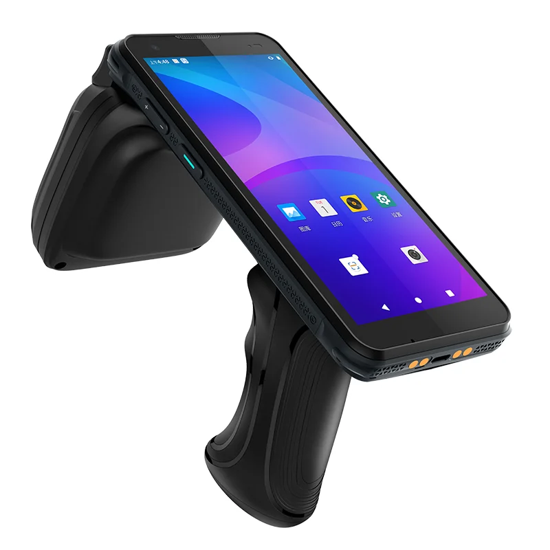
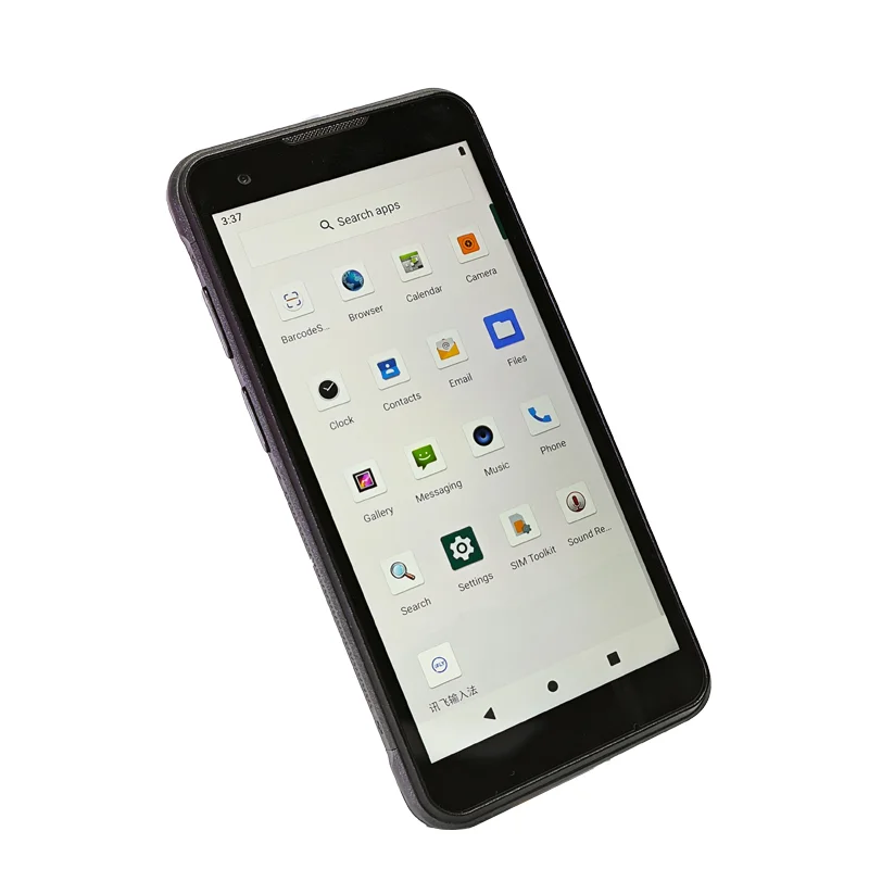
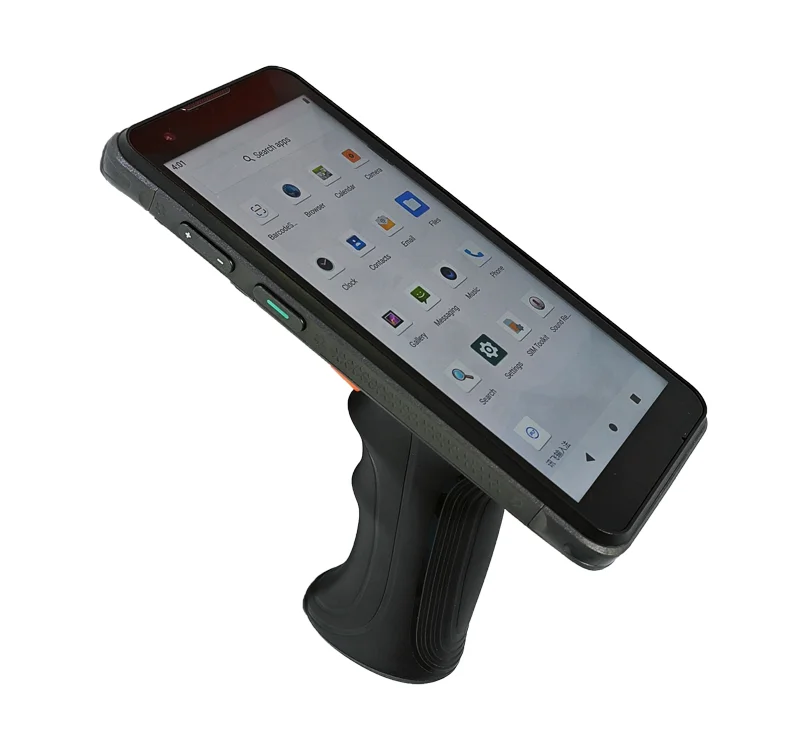
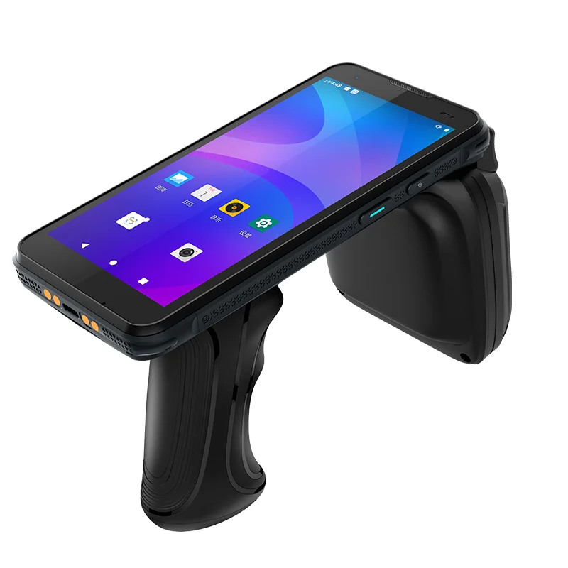
The supplied photographs show a handheld screen mounted above a pistol-style handle, including configurations with an additional rear housing. This form factor provides a useful reference for inventory and data-collection equipment where a trigger and a display are used together. The pictures establish the visible arrangement, not the accessory's radio technology, read range or electrical specification.
A handle can change how the operator presents the device, views a result and reaches the screen. The display discussion therefore needs to consider the complete held assembly, rather than treating the screen as an isolated rectangle. This application example examines those integration questions without claiming a documented customer deployment.
Design around the complete held assembly
Viewing position and UI orientation
The angled photographs show that the screen may be viewed while the terminal is tilted above the handle. Evaluate the candidate display and intended UI from realistic working positions. Confirm the required software orientation and how long identifiers, count totals and status messages appear at those positions. A device's resting angle in a photograph is not a measured viewing-angle specification.
Trigger use and touch access
Map which actions belong to the physical trigger and which require touch input. Then check whether the operator can reach the necessary controls while holding the assembled device. If a task requires the second hand, make that part of the workflow evaluation. Touch support with gloves or other conditions should be specified and tested separately.
Space for accessories, wiring and the display stack
Accessory housings and mounting points can constrain the space available around the display assembly. Review the enclosure, board and module drawings together to plan connector access, FPC routing and assembly clearance. The external photographs do not show the internal cable route, so they should not be used to assign a connector position or assume a compatible module.
Keep display selection separate from reader specifications
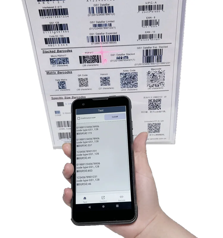
If the intended inventory project uses RFID, define the reader subsystem separately from the display module. Radio band, antenna configuration, read performance and regulatory requirements need their own project evidence. None of those characteristics are established by the handle shape. For a barcode-based configuration, the scan engine likewise requires its own specification.
The display review with Fuzheng can begin with the standard TFT-LCD module catalog, the target host interface and a drawing of the assembled terminal. Explain the intended holding position, UI content and touch method. Catalog records are references for comparison, not proof that a listed module is installed in the photographed equipment.
Sample evaluation checklist
- Evaluate the screen with the handle and intended accessories installed.
- Check record readability at the working distance and holding angles used in the task.
- Exercise trigger actions, touch entry and exception handling as one workflow.
- Confirm front-window alignment, mounting clearance and the planned FPC route.
- Verify host-interface compatibility and power requirements from the module documentation.
- Record unresolved display, mechanical and reader-system questions separately.
Prepare the next engineering discussion
Send front and side assembly drawings, the intended UI orientation, host-board interface and touch requirements. Include the accessory envelope and any constraints that cannot change. This allows the display conversation to focus on a reproducible configuration rather than an assumed match based on appearance.
Review the inventory and asset-tracking display requirements where relevant, and use the drawing and touch integration checklist to prepare the sample review.